GRW Spindle & Duplex Bearings
In the world of precision machining and micro-engineering, there comes a point where standard single-row bearings simply fall short on rigidity and bi-directional load capacity. This is where the real engineering begins, and where GRW Spindle and Duplex Bearings emerge as a critical, system-level solution.
They aren't simply two components working in parallel; they are a finely-tuned, integrated system. The secret to their success lies in preloading—the deliberate, engineered elimination of internal clearance to establish a defined contact angle. This creates a kind of built-in tension, bringing the entire system to a zero-clearance state of readiness. Let's explore the mechanics of this system and the pivotal role preload plays in its performance.
1. The Art of the Pair: Three Classic Configurations
GRW achieves duplexing by precisely grinding the faces of the inner and/or outer rings. This allows two bearings to be mounted in configurations like "back-to-back" or "face-to-face" with a specific preload force. While duplexing dramatically increases system stiffness, it comes at the cost of increased friction and heat. Understanding these arrangements is the first step toward a successful design.
- DB (-1) | Back-to-Back (O-Arrangement)
- How it Works: The load lines diverge, much like two hands pushing outward to create the most stable base.
- Strengths & Characteristics: This "O-arrangement" offers the highest resistance to moment loads (tilting forces), providing excellent stability under eccentric loads. It is the most common configuration for rigid spindles.
- Note: Requires precise clamping of the inner rings for proper function.
- DF (-2) | Face-to-Face (X-Arrangement)
- How it Works: The load lines converge inward, forming an "X-arrangement."
- Strengths & Characteristics: This layout is more tolerant of shaft misalignment and is often easier to assemble, as the outer ring faces are clamped together.
- The Trade-off: It offers lower resistance to moment loads compared to the DB configuration.
- DT (-3) | Tandem (>>-Arrangement)
- How it Works: Both bearings are mounted in the same direction to share a heavy axial load from a single direction.
- Application: This is a specialist configuration. It cannot generate preload on its own and must be used in conjunction with another bearing or pair (typically DB or DF) to provide preload in the opposing direction.
- U (-4) | Universal Matching
- The Choice for Flexibility: These bearings are specially ground to be assembled in any configuration (DB, DF, or DT) without performance loss, offering maximum design and assembly freedom for the end-user.
2. The Preload Dilemma: A Double-Edged Sword of Performance and Lifespan
Preload is the most critical and misunderstood parameter in a spindle bearing application. It directly dictates the bearing's operating clearance, system stiffness, and, crucially, its operating temperature.
A time-tested rule of thumb is:
Fv ≈ Fa / 3
This means the applied axial preload (Fv) should not exceed one-third of the maximum expected working axial load (Fa).
Why is this a "rule"? If preload is too high—or if it exceeds the operational load—the bearing can suffer from "false brinelling" at startup or low loads. This excessive friction leads to thermal runaway, resulting in catastrophic premature failure.
To simplify selection, GRW provides standardized preload classes:
- Light (L): The standard for high-speed applications where minimizing heat generation is paramount.
- Medium (M): The gold standard for general-purpose machine tools, striking a balance between speed and stiffness.
- Heavy (S): Used for applications demanding maximum stiffness where high speed is a secondary concern.
Expert Advice: Always opt for the lowest preload that satisfies the stiffness requirements of your machine structure. Excessive preload dramatically increases starting torque and shortens bearing life—a critical design trap to be avoided at all costs.
3. The Essence of Geometry: Choosing Between 15° and 25° Contact Angles
GRW's Spindle Bearings (7000 series) are angular contact bearings optimized for high-speed rotation. Their defining feature is the Contact Angle (α).
- 15° (C): The Speed and Rigidity Balancer
- As the standard angle, it provides a well-balanced ratio of radial and axial load capacity, making it ideal for most high-speed spindles.
- 25° (E): The Axial Stiffness Specialist
- Compared to the 15° version, this angle offers higher axial stiffness and greater axial load capacity, but at the expense of some radial load capacity.
How to Decide?
The choice depends entirely on your primary load type. For applications dominated by axial thrust (e.g., drilling), the 25° angle is the stronger choice. For those dominated by radial forces (e.g., side-load from milling), the 15° angle performs better. It's important to remember that a larger contact angle results in greater internal axial displacement for a given radial load, a factor that must be considered in the design.
4. Not All Pairs Are Created Equal: Deep Groove vs. Angular Contact Duplex
This is a common point of confusion. GRW offers two distinct types of duplex bearings for very different applications:
- Deep Groove Radial Duplex:
- What they are: Essentially standard radial bearings that have been face-ground to enable preloading.
- Features: They typically use a larger radial play than standard bearings to allow a contact angle to form when preloaded.
- Use Case: General instrumentation where absolute rigidity is not the primary concern and some residual radial play is acceptable.
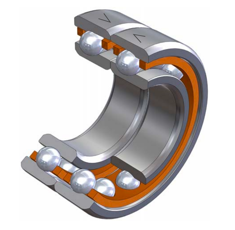
- Spindle/Angular Contact Bearings:
- What they are: Purpose-built for ultimate rigidity and speed.
- Features: They have non-separable rings (often with a partial shoulder) and are equipped with solid phenolic or XTRAlon retainers designed for advanced oil-jet or oil-air lubrication.
- Use Case: High-speed machining centers, dental turbines, and aerospace actuators—top-tier applications with stringent demands on both stiffness and speed.
5. The Red Line of Speed: Understanding Thermal Reference Speed (n_th)
When pushing bearings to their performance limits, the Thermal Reference Speed (n_th) becomes a critical metric. It's not an absolute "do-not-exceed" limit, but a crucial engineering benchmark.
It defines the rotational speed at which the heat generated by friction within the bearing equals the heat dissipated through the shaft and housing.
In real-world scenarios, advanced lubrication (like oil-air) and ceramic balls (Si3N4) can allow the limiting speed to significantly surpass the catalog rating. However, if the operating speed consistently exceeds the thermal reference speed, the bearing will generate more heat than it can shed, causing temperatures to climb uncontrollably until seizure occurs.
Designing with GRW spindle bearings requires a fundamental shift in mindset—from simple "component selection" to "systems engineering." By deeply understanding the interplay between DB/DF configurations, the subtle trade-offs of 15° vs. 25° contact angles, and the precise calculation of preload, engineers can extract the maximum stiffness and speed from their spindles. Always remember: in high-precision applications, the limiting factor is rarely the steel itself—it is our ability to manage the thermal consequences of preload.